#FeaturedJobFriday: 134-Year-Old Brick Sewer Outflow System Repair
Sewer Outflow Rehabilitation: Atlas Systems of New England
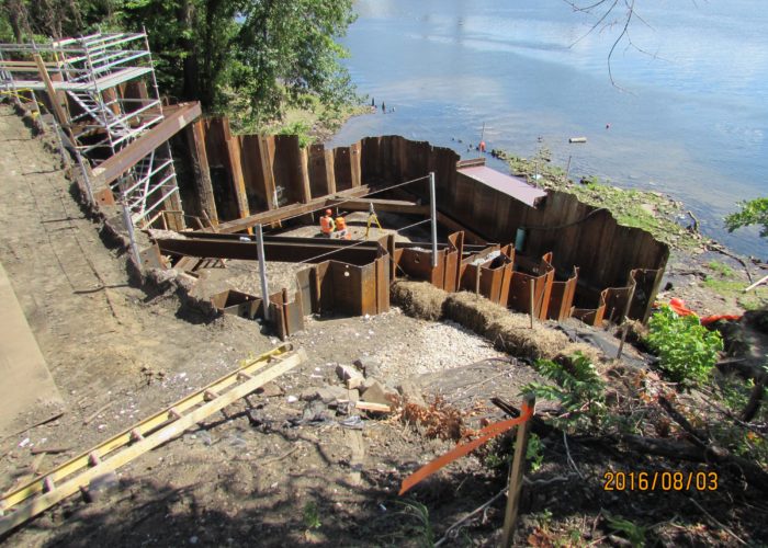
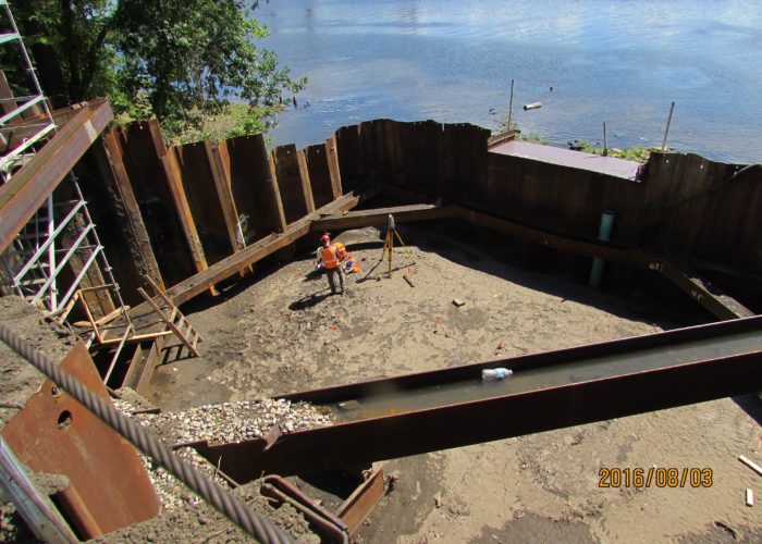
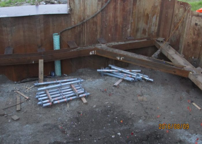
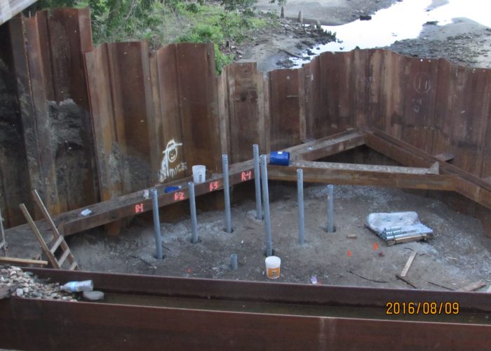
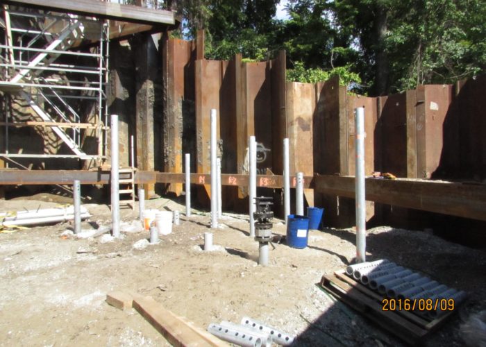
The City of Springfield, Massachusetts initiated the Connecticut River Combined Sewer Outflow (CSO) Rehabilitation Project. This was prompted by the dire disrepair of a 134-year-old brick sewer outflow system and headwall. The project called for the removal of the headwall and relining the brick sewer pipe. Because the outflow was on the banks of the Connecticut River and the steep slope the City of Springfield Engineers opted to use ECP helical piers due to the minimal invasiveness to the environment, speed of installation, verifiable capacities and size of equipment.
Prior to starting the project, Atlas Systems of New England was provided with a 2014 geotechnical report with soil borings in the approximate vicinity of where the piers were to be installed. With this information, they hired Jay Perkins, PE a geotechnical engineer with Brierley Associates to design the helical pier systems.
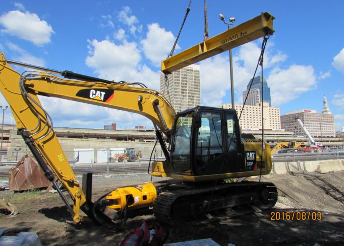
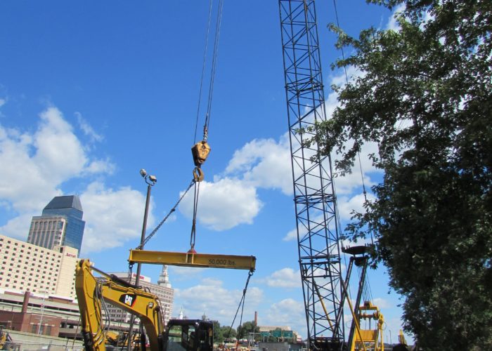
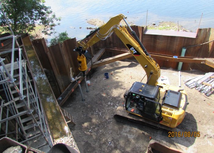
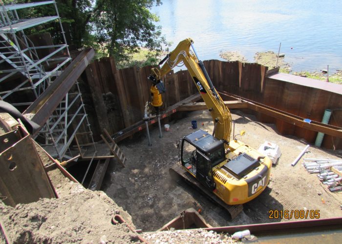
The design was completed and approved by the City of Springfield engineers (Kleinfelder Associates). They then proceeded with the start of the project. Due to the high minimum torques necessary to achieve the required capacities additional equipment needed to be procured, a 30,000 ft-lb gear-motor and CAT-313 excavator. The installation of the piers at the bottom of the coffer dam necessitated craning all equipment in and out daily. This added an extra hour to both the start and end of each workday.
Also, constant weather monitoring was essential because the working CSO in one coffer dam could overflow within 7 minutes.
Major Challenges for the Sewer Outflow Project
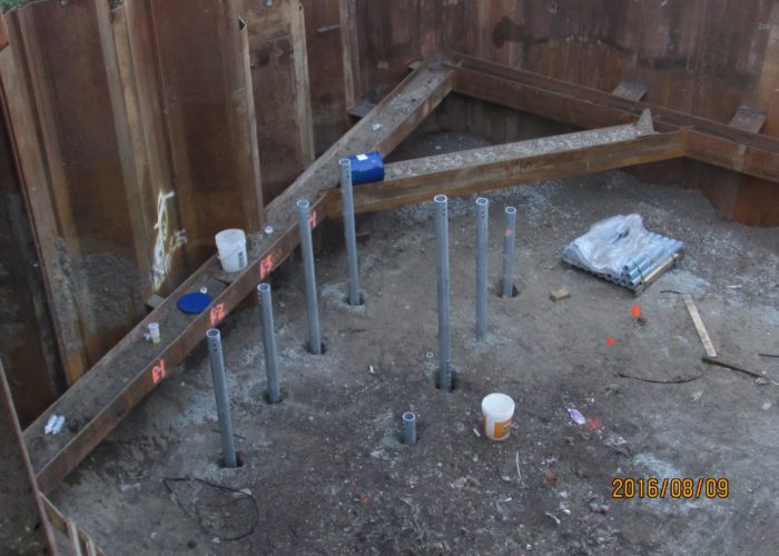
They had to crane equipment and materials in and out of the coffer dam daily. Their challenges also involved meeting required torques and depths from the original soil borings. Atlas started installing the helical piers in designated locations with a target depth of 34 feet below the base of the coffer dam. This was done with minimum torque requirements of 20,000 ft-lbs for the 4 ½” round shaft and 14,300 ft-lbs for the 2” square bar. During the installation, it was observed that the design requirement for depth and torque were not being achieved. The piers were going far deeper and torques were significantly less (< 13,000 ft-lbs) than their approved design.
After discussion with the owner’s engineers and our geotechnical engineer, it was determined that the soil borings used in our design were not relevant to where the piers were being installed. The borings were over 100 feet away with a difference of 40 feet in elevation from where the piers were being installed. This put the project on hold until new borings could be taken within the coffer dam. With new soil boring and a design review it was discussed that a suitable layer of bearing soil was identified at a new depth and the piers should seat in that layer regardless of torque.
Even with this new data, their torques were significantly less than what their empirical formulas determine as minimum torques. Numerous discussions were had regarding the relationship between N values and torque with no easily explainable explanation as to why there was such a discrepancy. The outcome was for a series of compression and tension load tests be conducted on several helical piles.
Due to the limited space in the bottom of the coffer dam, the load test had to make use of production piers as both test pier and reaction piers. This eventually required modifying the test frame on order to use existing piers as reaction anchors. The results of the load tests were positive and new installation criteria was established for the installation of the helical piers going forward. Their load tests included both the 4 ½” round shaft for compression and the 2” square bar for compression and tension. Each of these piers were being tested close to their maximum design criteria yet achieved the required design capacity.
Even within the coffer dam the soil characteristics were different from one side to the other, even right next to the soil boring that was taken in the coffer dam. They did experience a strange and inexplicable occurrence with one of their piers (2” square bar). After installing the pier, the soil around the shaft started to “boil” up and continued expelling soil for as long as the helical pier was embedded. No one could provide an explanation as to why this was occurring. This did cause concern regarding the design of the coffer dam as would the continued “boil” of the soil undermine the toe of the sheet piles used to construct the dam?
Solutions for these Challenges
The use of the ECP helical pier systems allowed the rehabilitation to be completed with minimal disturbance to the environment in an environmentally sensitive area along the Connecticut River banks. Utilizing the helical piers allowed for quick installation of deep foundation support and minimizes costs. Due to the high required capacity the project should have reduced the pile capacity and added more piers.


